
A Dynamic Journey of Distributed Antenna Systems From Single Carrier Systems to All-Fiber Infrastructure
The evolution of Distributed Antenna Systems (DAS) reflects a dynamic journey from the foundational DAS 1.0, reliant on coaxial cable technology, to the hybrid DAS 2.0, incorporating both coaxial and fiber optics. DAS 1.0, characterized by simple yet effective signal boosting through coaxial cables and directional antennas, primarily served single carriers (such as Verizon, AT&T, etc).
DAS 2.0 introduced a more versatile approach with a mix of coaxial and fiber components, laying the groundwork for enhanced signal distribution. This transition ushered in components like converters, antennas, connectors, and couplers, forming the comprehensive system of DAS 2.0.
Building upon this progression, DAS 3.0 emerges as the next-generation solution, marked by an all-fiber architecture and a sophisticated configuration of head-end electronics, fiber distribution, remotes, and a network expansion unit.
DAS 1.0 | BDA-Based Coaxial DAS
The first generation of DAS – also known as DAS 1.0 – relied on coaxial cable technology. In this configuration, the DAS functioned with a signal booster or repeater – an electronic device designed to amplify or repeat signals.
The operational principle was straightforward – the system borrowed a signal, amplified it, and distributed it where needed. These uncomplicated setups are called passive DAS or Bi-directional Amplifier (BDA)-based coaxial DAS.
More specifically, a directional antenna would typically be installed on the building’s roof to transmit and receive signals in specific directions. For instance, if the intention was to enhance the Verizon signal, aligning the directional antenna with a Verizon cell tower rather than an AT&T tower was crucial.
The directional antenna captured or received the signal from the cell tower, and this signal traversed a coaxial cable inside the building to reach a signal booster, also known as a BDA, repeater, or amplifier.
The amplified signal was then distributed within the building through coaxial cables and antennas strategically placed where signal coverage was required. Although the diagram displays only two antennas, the actual number can vary based on the specific needs, ranging from one to multiple antennas.
It’s important to note that most DAS 1.0 systems are designed as single-carrier DAS, primarily handling one carrier or operator, such as Verizon. While exceptions exist, constructing carrier-grade multi-carrier DAS in all-coax systems is rare.

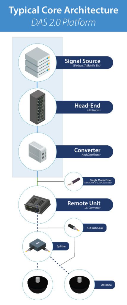
Core Architecture of DAS 2.0
The RF signal source starts from the top of the diagram. The RF signal travels through coaxial cables and connects to the DAS via coaxial cable connectors. Next, the signal enters the DAS Head-end, a collection of electronics responsible for signal preparation and distribution. This includes converting RF signals to optical for fiber distribution. The initial converter within the head-end handles this task.
Within the head-end, two key components are often present:
- DAS Tray: Used to regulate high-power signals from sources like base stations, ensuring compatibility with the DAS.
- RF Interface Unit: Receives the signal from the source and forwards it to the converter for distribution.
The converter distributes optical signals to multiple remotes strategically positioned throughout the building. These remotes convert optical signals back to RF in various locations.
Engineers utilize software like iBwave to determine optimal remote placements. Fiber lengths between converters vary, ranging from short to extensive distances. Single-mode fibers with SC/APC or LC/APC connectors are typically used.
The RF signal is converted back to its original form at the remote sites and transmitted to antennas via coaxial cables, typically ½” in diameter. Depending on engineering preferences, splitters or couplers may distribute the RF signal among multiple antennas connected to a single remote.
DAS 2.0 | Common Components Used
While DAS 1.0 relied solely on coaxial cable technology, DAS 2.0 is a blend of coaxial and fiber optics. An easy way to remember the five most common components that constitute a DAS 2.0 system is through the 4Cs and 1 A (C-C-A-C-C): Cabling, Converters, Antennas, Connectors, and Couplers.
Cable (Coaxial and Fiber)
Coaxial and fiber cables form the backbone of DAS.
Coaxial Cable
Coaxial cables are designed for transmitting and receiving RF signals. In a cross-section, you’ll find a center conductor surrounded by an insulator, a metal shield, and an outer plastic jacket.
While larger than typical cable TV coax, these cables (often blue and ½” inch in diameter) have a limitation – they experience significant signal loss over extended lengths, typically losing 50% of signal strength every 100 feet.
Fiber Optic Cable
Fiber, with a glass core, is a preferred medium for DAS. Unlike coax, fiber transports optical signals over long distances with minimal signal loss, making it an ideal solution for spanning multiple buildings in a commercial campus.
Converters
These devices facilitate the conversion of RF signals to optical signals and vice versa. They play a crucial role in combining the strengths of coaxial cables for RF transport and fiber optics for long-distance signal transmission.
Antennas
Antennas are essential for broadcasting RF signals. There are two common types: Omni antennas, which radiate signals in all directions, and directional antennas, which focus signals in specific directions. They connect to coaxial cables, enabling efficient signal transmission.
Connectors
Connectors are vital components linking devices and cables. Two types are used: Coaxial connectors for connecting coax cables and antennas and fiber connectors for linking fiber cables. Special tools are often required for connecting in the field.
Common Coax Connectors
DIN, Mini-DIN, N-type, and SMA/QMA are commonly used connectors for DAS. Each serves specific purposes, with considerations for factors like RF power and interference.
Common Fiber Connectors
SC-APC and LC-APC are the predominant fiber connectors in DAS, with differences in their polished surfaces affecting signal transmission.
Couplers
Couplers, including splitters, directional couplers, and hybrid couplers, play a role in managing signal distribution. Splitters divide RF signals evenly, directional couplers split signals unevenly, and hybrid couplers combine and distribute signals. Splitters come in various shapes and sizes, such as 2-way splitters, and directional and hybrid couplers aid in managing RF feeds through multiple input and output connectors.
DAS 3.0 | Next Generation DAS and Its Core Architecture
DAS 1.0 exclusively utilized coaxial cables, DAS 2.0 introduced a combination of fiber and coax, and DAS 3.0 represents the next evolutionary step with an all-fiber DAS.

Signal Source
The signal source, often a base station from an operator or carrier, feeds signals via short coaxial jumpers into the head-end electronics, typically located in the Main Distribution Frame (MDF).
Head-End Electronics
Head-end electronics serve two major functions: preparing the RF signal for system-wide distribution and converting the RF signal to an optical signal for fiber distribution. These electronics, clustered on cards, are crucial components.
Fiber Distribution
From the head-end electronics, single-mode fiber fans out to multiple remotes. These remotes are commonly ceiling-mounted, and the diagram depicts one remote, but there will be multiple remotes in practice.
Network Expansion Unit
To extend coverage to another building, one or two strands of single-mode fiber run from the head-end electronics to a Network Expansion Unit, often rack-mounted in the MDF closet of the additional building. This unit replicates the architecture, enabling fiber distribution to multiple remotes.
Power Supply
All electronics require a power source. Remotes are often powered via copper wire or CAT5 from an Intermediate Distribution Frame (IDF) closet’s Power Supply Unit (PSU). Some DAS OEMs provide hybrid fiber with fiber strands and copper for power within the same jacket.
Key Features of DAS 3.0 Architecture
- 1 head-end equipment supports multiple remotes.
- 1 network extension unit supports multiple remotes.
- A single system can cover a large or multiple campus buildings.
- Remotes are typically ceiling-mounted.
- Remotes may connect to optional antennas via coax jumpers.
- Power to remotes can be supplied via copper (e.g., CAT5) from IDF closets.
About MCA
MCA is one of the largest and most trusted DAS integrators in the United States, offering world-class voice, data, and security solutions that enhance the quality, safety, and productivity of customers, operations, and lives.
More than 65,000 customers trust MCA to provide carefully researched solutions for a safe, secure, and more efficient workplace. As your trusted advisor, we reduce the time and effort needed to research, install, and maintain the right solutions to improve your workplace.
Our team of certified professionals across the United States delivers a full suite of reliable technologies with a service-first approach. The MCA advantage is our extensive service portfolio to support the solution lifecycle from start to finish.
