
Over A Century Of Trusted Communication Technology
Since the 1880s, when it was proven that radio waves could be wirelessly transmitted over short distances, utilizing radio waves and frequencies has become an integral part of our society.
Since the 1880s, when it was proven that radio waves could be wirelessly transmitted over short distances, utilizing radio waves and frequencies has become an integral part of our society.
Since radio frequency (RF) lies at the heart of our ability to tune into specific radio broadcasts, accurate testing and setup are essential for optimal performance.
Designing Distributed Antenna Systems (DAS) And Site Surveys
Site surveys are a fundamental component of the Distributed Antenna System (DAS) design process since they provide the critical information necessary to create an effective and efficient system. By conducting the surveys, implementers receive the answers to essential questions such as the current state of signal coverage within a building and the required coverage levels to meet specific goals. Engineers can also collect detailed data that forms the foundation for designing a system tailored to the unique needs of each floor and area within the building.
During a site survey, two primary types of data are collected: benchmark or base signal measurements and detailed building information. Benchmark Signal Measurements reveal the existing signal coverage in the building, typically gathered using advanced signal scanners and specialized software to ensure accuracy and comprehensiveness. Additionally, collecting detailed building information, such as architectural layouts and materials, helps engineers understand potential signal obstacles and propagation characteristics.
Together, these data sets enable the precise engineering and design of the DAS, ensuring optimal coverage and performance tailored to the specific environment.
What Is RF Benchmark Testing?
Ensuring efficient frequency usage and compliance with regulations, RF testing plays a vital role in verifying the performance of your radio broadcasts. This essential testing covers a wide range of broadcasts, including Wi-Fi, GPS, PMR, LMR, and cellular frequencies. When looking to adhere to frequency coverage standards, mandated by law in most markets, proper RF testing is crucial to understanding how signals propagate within your buildings.
Building owners and property managers must meet RF standards across different jurisdictions with varying regulations. To ensure compliance, it is imperative to conduct targeted testing aligned with your specific locality. RF testing evaluates key aspects of your existing in-building wireless communications systems and evaluates the need for new systems should no legacy systems exist and when legacy systems are no longer helping meet your needs or code requirements, such as output power, receiver and transmitter performance, sensitivity, and blocking.
The testing procedures for RF vary depending on the applicable standards for your desired frequency ranges, often set by organizations like the IFC, NFPA, and limited cases, even by OSHA. By conducting comprehensive RF testing, you can ensure regulatory compliance, prioritize device safety, and optimize overall performance.
Benchmarking Tools
There are numerous tools available in the market for benchmarking signal measurements. Typically, this equipment uses a scanner, receiver, or phone to detect signals at various points on the floor, then plots this information onto the floor plan.
Standard tools for large areas like venues include Qualipoc, JDSU or VIAVI, TEMS, NEMO, XCAL, PCTEL, and Solutelia equipment. These tools combine hardware, such as laptops with dongles and scanners, with software that captures and maps signals over a floor plan. For example, at MCA, we utilize the iBFlex Scanner from PCTEL along with WINd Pro software from Solutelia for data collection and reporting.

Performing RF Tests
To conduct an RF test, the device is placed in an isolated area with controlled conditions to minimize electromagnetic interference. The device is then closely monitored for any emissions that could disrupt other nearby devices.
Additionally, testing can be conducted to assess the device’s RF immunity, which measures its ability to handle interference from other devices. This testing involves subjecting the device to various interferences and evaluating its performance under such conditions.
In the case of Cellular and Public Safety RF testing, RF benchmark testing most commonly involves capturing multiple measurements, including signal strength, signal-to-noise ratio, signal quality, and data transfer rates from RF sources outside of buildings and those being transmitted within them. These measurements are systematically collected at various locations throughout the test area to provide a holistic view of the network’s performance and gather comprehensive data.
RF Test Objectives
RF tests ensure that existing communications enhancement systems comply with specific guidelines regarding wavelengths and emission strength as mandated by government regulations.
After extensive data analysis, engineers create a heat map of the ambient signal. Multiple plots are generated for each floor. For instance, the sample layout below shows a color-coded output of a signal parameter known as LTE RSRP, indicating the strength of the LTE signal on that floor. LTE RSRP is just one of the many data sets collected.

One of the most common non-compliance issues is attenuation – the loss of signal strength during a broadcast. Signal attenuation often occurs due to physical obstructions, such as walls or floors, which impede signal propagation or from interference between signals occupying the same wavelength and frequency, which can lead to signal loss.
Proper testing can identify signs of potential issues related to attenuation. For instance, a device broadcasting with excessive power for its designated range may overpower other signals within that bandwidth, resulting in attenuation and the signal bleeding into other broadcasts. Proper RF testing would identify this situation and allow the provider or operator to remedy it.
Determining Coverage Goals
The RF Test/benchmark survey helps understand a building’s existing signal coverage so that the required coverage can be achieved. Once the coverage goal is set, engineers can design a DAS that meets these requirements.
Carrier or Operator Standards
Each carrier, such as AT&T or Verizon, has its coverage standards. For example, one operator’s standard might require that if UMTS technology is added at 1900 and 2100 MHz frequencies, the signal strength parameter (RSCP) must be at least -85 dBm or 8 dB stronger than the macro network across 95% of the coverage area. This means the DAS should boost the incoming signal by 8 dB inside the building. Understanding decibel math is crucial here, as an 8 dB increase represents a signal strength roughly four times greater than the signal coming from the macro network. Engineers need to be well-versed in these standards to ensure compliance.
Business Factors
Business considerations also play a significant role in determining coverage goals. Some of the key considerations include:
- What type of service does the customer need? For instance, if a customer only requires coverage for voice calls and not for data, a simpler and less costly DAS might suffice, especially if the company already has a robust WiFi system.
- What coverage makes business sense? Providing just enough signal for voice calls is often cheaper than deploying an advanced DAS necessary for high data rates.
Ultimately, it’s a balance between budget and coverage needs. A business funding its own DAS might opt for coverage only in critical areas, such as office spaces, rather than the entire building. Engineers must assess the customer’s specific coverage requirements before commencing the design phase.
Collecting Building Information
In addition to benchmark signal data, engineers gather two types of building information during a survey.
Information Type 1: Construction and Logistics
This category includes details that affect the construction process and logistics, such as:
- Point of Contact (POC) and access information
- Badging and escorting protocols
- Safety training requirements
- Working hours
- Material staging
- Infectious control measures and HEPA filter requirements (for hospitals)
- Other relevant information
Information Type 2: Design and Materials
This type of information impacts the design and materials needed for the project, including:
- Head-end room and remote locations (MDF and IDFs)
- Electrical information
- GPS or donor location
- Cable routes and support within the building
- Floor-to-floor penetration
- Fiber layout, and more
Both types of information are crucial for developing the design, selecting materials, and estimating construction costs accurately.
Identifying RF Interference
Accurately identifying RF interference requires first narrowing down the specific type of interference experienced, categorized as Narrow Band or Broadband.
Narrow Band Interference
Narrow Band interference affects broadcasts with short, narrow wavelengths, such as co-channel and adjacent-channel transmissions.
Broadband Interference
Broadband interference, the more familiar type, involves larger wavelengths seen in digital television broadcasts, Wi-Fi networks, cellular devices, and Bluetooth connections.
The exact source and nature of potential interference can be determined by conducting tests on both frequency ranges. For instance, narrow band interference may result in Adjacent-Channel Interference, where two channels with similar frequencies bleed into each other.
Thorough testing can pinpoint these issues before strategic device deployment, ensuring a smooth installation and implementation within your buildings and facilities.
Engineering A Distributed Antenna System (DAS)
Having determined the existing signal coverage and identified the coverage requirements, the next step involves the engineering process to provide the desired coverage.
Link Budget and Propagation Analysis
These analyses are crucial for engineering. The Link Budget calculates the system’s gains and losses to determine the power that will reach a phone from an antenna. Propagation Analysis predicts how far the signal will travel and where to place antennas to ensure seamless coverage.

Survey and Engineering Deliverables
The main deliverables from the survey and engineering processes are construction-ready documents. These comprehensive documents and analyses ensure that the DAS is designed to meet coverage requirements effectively and safely.
Logical Diagram
An overview of the DAS from the head-end to antennas, showing all connections and power levels.
Floor Plans with Device Locations
These plans, essential for construction, show antenna and electronic device placements, cable routes, and floor penetration points.
Bill of Materials (BOM)
Lists all materials and devices needed for the DAS, including parts, descriptions, and quantities.


Additional documents that support the construction and validation process include:
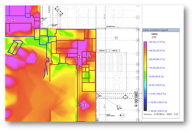
- Propagation Plots: Predictive heat maps showing expected signal coverage.
- SINR Plots: Indicate signal quality, with higher values representing better quality.
- MAX Data Rate Plots: Predict maximum data rates and modulation schemes.
- EMF Reports: Assess the electromagnetic field exposure to ensure compliance with FCC guidelines and public health safety.

Superior RF Benchmark Testing and In-Building Wireless Solutions from MCA
Facility owners, operators, managers, and builders need a trusted partner to conduct RF benchmark testing and design top-notch distributed antenna systems for buildings. Look no further than MCA’s In-Building Wireless Solutions (IWS) team.
MCA’s IWS team brings extensive expertise and experience in delivering the best and most thorough RF benchmark testing services. They understand the critical importance of reliable in-building wireless connectivity and its impact on operations, communication, and safety.
By collaborating with MCA’s IWS experts, facility stakeholders can ensure that their buildings have the most optimal distributed antenna systems. MCA’s team conducts comprehensive RF benchmark testing, capturing valuable insights into signal strength, coverage gaps, and areas requiring enhancement.
With MCA as your partner, you can expect meticulous analysis, cutting-edge tools, and specialized software to evaluate the performance of your in-building wireless systems. The IWS team will work closely with you to tailor solutions that align with your specific needs, compliance requirements, and industry standards.
Don’t settle for subpar in-building wireless solutions. Trust MCA’s IWS team to provide you with the expertise, support, and guidance needed to achieve seamless connectivity, efficient operations, and enhanced user experiences. Experience the difference MCA can make in optimizing your building’s wireless capabilities.
<< Learn More About MCA RF Benchmark Testing Services >>
About MCA
We believe every workplace should be safe, secure, and efficient. As trusted advisors, we deliver integrated communication, connectivity, and security solutions with a Service First mindset – driven by a team that cares deeply about our customers and each other.
Why MCA? At MCA, we help solve critical communication, connectivity, and security challenges with turnkey, integrated system solutions – from two-way radios and in-building wireless to video surveillance, access control, and more. MCA is built from over 50 companies with deep technical expertise and strong local roots. And we’re still growing – expanding our capabilities, our reach, and our team.
Our 100+ Solution Centers bring together sales, installation, service, and customer operations teams to deliver seamless, nationwide support. Guided by our Service First value, we don’t just connect the wires and walk away – we provide customized solutions backed by deep expertise and lifecycle support.
